
Chapter 1: Setting Up the Underlay for EVPN VXLAN Fabric
Objective
This lab focuses on configuring the IP network underlay required for an EVPN VXLAN fabric. Participants will learn to establish a scalable and resilient underlay using OSPF as the Interior Gateway Protocol (IGP).
The lab covers critical aspects such as IP addressing strategies for point-to-point links and loopback interfaces, MTU considerations for VXLAN traffic, and OSPF configuration best practices in a spine-leaf topology.
By the end of this lab, participants will have a fully functional OSPF-based underlay, providing the necessary reachability for VTEP communication.
Key Features Implemented
IP Addressing Strategy:
- Loopback interface configuration for Router IDs (RIDs) and VTEP source interfaces.
- Learner's choice of point-to-point link addressing:
/30subnets/31subnets- IP Unnumbered
MTU Configuration:
- Setting appropriate MTU on fabric links to accommodate VXLAN overhead.
OSPF as Underlay IGP:
- Configuration of OSPF in a spine-leaf topology.
- Utilizing OSPF point-to-point network type on inter-switch links.
- Ensuring full reachability for all underlay infrastructure IPs.
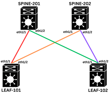
Topology
This lab utilizes a standard spine-leaf Clos topology based on the provided diagram:
Configuration Tasks
Task 1: Configure hostnames on all switches.
(No specific example given, assume standard hostname configuration commands per vendor.)
Task 2: Loopback Interface Configuration
- Set up Loopback0 as the VTEP source on all leaf switches, using the format
10.200.200.xxx/32, where xxx corresponds to the Spine or Leaf number. - Set up Loopback1 for OSPF Router ID on all switches, using the format
10.1.1.xxx/32, where xxx corresponds to the Spine or Leaf number.
Task 3: Point-to-Point Link IP Addressing (Learner's Choice)
Assign IP addresses to all spine-leaf physical links using subnets from the 10.1.1.0/24 network range, selecting one of the available methods for addressing.
- Option A: Using
/30Subnets- Example for LEAF-101 (Ethernet1/1) to SPINE-201 (Ethernet1/1): Network:
10.2.101.0/30
- Example for LEAF-101 (Ethernet1/1) to SPINE-201 (Ethernet1/1): Network:
- Option B: Using
/31Subnets- More efficient for point-to-point links, providing 2 usable IPs. (RFC 3021)
- Option C: Using IP Unnumbered
- Conserves IP addresses by "borrowing" an IP from a loopback interface.
Task 4: MTU Configuration
- VXLAN introduces about 50-54 bytes of overhead. To prevent fragmentation and accommodate potential jumbo frames, set the MTU to
9216on all spine-leaf physical interfaces.
Task 5: OSPF Underlay Configuration
- Enable the OSPF feature.
- Configure the OSPF routing process named "UNDERLAY", and assign the Loopback1 IP address as the router ID on all switches.
- Enable OSPF on Loopback interfaces, advertising Loopback networks on all switches into OSPF Area 0.
- Enable OSPF on Spine-Leaf physical interfaces (Ethernet1/1 and Ethernet1/2, as applicable per device) and add them to OSPF Area 0, ensuring the OSPF network type is set to point-to-point.
Final Configurations
Want to take a look for yourself? Here, you will find the final configurations of each device required for this lab.
hostname LEAF-101

interface loopback0
  ip address 10.200.200.101/32
  ip router ospf UNDERLAY area 0.0.0.0

interface loopback1
  ip address 10.1.1.101/32
  ip router ospf UNDERLAY area 0.0.0.0

interface Ethernet1/1
  no switchport
  mtu 9216
  medium p2p
  ip unnumbered loopback1
  ip ospf network point-to-point
  ip router ospf UNDERLAY area 0.0.0.0
  no shutdown

interface Ethernet1/2
  no switchport
  mtu 9216
  medium p2p
  ip unnumbered loopback1
  ip ospf network point-to-point
  ip router ospf UNDERLAY area 0.0.0.0
  no shutdown

feature ospf

router ospf UNDERLAY
  router-id 10.1.1.101
hostname LEAF-102

interface loopback0
  ip address 10.200.200.102/32
  ip router ospf UNDERLAY area 0.0.0.0

interface loopback1
  ip address 10.1.1.102/32
  ip router ospf UNDERLAY area 0.0.0.0

interface Ethernet1/1
  no switchport
  mtu 9216
  medium p2p
  ip unnumbered loopback1
  ip ospf network point-to-point
  ip router ospf UNDERLAY area 0.0.0.0
  no shutdown

interface Ethernet1/2
  no switchport
  mtu 9216
  medium p2p
  ip unnumbered loopback1
  ip ospf network point-to-point
  ip router ospf UNDERLAY area 0.0.0.0
  no shutdown

feature ospf

router ospf UNDERLAY
  router-id 10.1.1.102
hostname SPINE-201

interface loopback1
  ip address 10.1.1.201/32
  ip router ospf UNDERLAY area 0.0.0.0

interface Ethernet1/1
  no switchport
  mtu 9216
  medium p2p
  ip unnumbered loopback1
  ip ospf network point-to-point
  ip router ospf UNDERLAY area 0.0.0.0
  no shutdown

interface Ethernet1/2
  no switchport
  mtu 9216
  medium p2p
  ip unnumbered loopback1
  ip ospf network point-to-point
  ip router ospf UNDERLAY area 0.0.0.0
  no shutdown

feature ospf

router ospf UNDERLAY
  router-id 10.1.1.201
hostname SPINE-202

interface loopback1
  ip address 10.1.1.202/32
  ip router ospf UNDERLAY area 0.0.0.0

interface Ethernet1/1
  no switchport
  mtu 9216
  medium p2p
  ip unnumbered loopback1
  ip ospf network point-to-point
  ip router ospf UNDERLAY area 0.0.0.0
  no shutdown

interface Ethernet1/2
  no switchport
  mtu 9216
  medium p2p
  ip unnumbered loopback1
  ip ospf network point-to-point
  ip router ospf UNDERLAY area 0.0.0.0
  no shutdown

feature ospf

router ospf UNDERLAY
  router-id 10.1.1.202
Verification Commands
show ip interface brief || show interface Ethernet1/1- Verify IP Interfaces and MTU.
show ip ospf neighbor- Verify OSPF Neighbors.
show ip ospf interface brief || show ip ospf interface Ethernet1/1- Verify OSPF Interface Configuration. (Expected: Network Type should be P2P for spine-leaf links)
show ip route || show ip route ospf- Verify OSPF Routing Table. Ensure all Loopback0 and Loopback1 IPs are learned.
- Ping Commands (for End-to-End Reachability)
- Verify End-to-End Reachability (Critical for VTEPs). Ping between Loopback0 interfaces of LEAF-101 and LEAF-102.
- Ping from any switch to any other switch's Loopback1.
- Example:
ping 10.200.200.102 source 10.200.200.101(adjust IPs as per your config)
show running-config ospf- Review OSPF Configuration.
Expected Outcomes
- All Spine and Leaf switches (SPINE-201, SPINE-202, LEAF-101, LEAF-102) have correct IP addresses configured.
- MTU on all spine-leaf physical interfaces (e.g., eth1/1, eth1/2 on relevant devices) is set to the configured jumbo value (9216).
- OSPF adjacencies are
FULLbetween all directly connected Spine and Leaf switches. - OSPF network type for all spine-leaf interfaces is
POINT_TO_POINT. - OSPF routing tables contain routes to all Loopback0 (VTEP source IPs) and Loopback1 (RIDs).
- Full IP reachability is confirmed between all Loopback0 interfaces and, critically, between Loopback1 interfaces on LEAF-101 and LEAF-102 (and other switch loopbacks).
